We are no longer offering this product.
The below information is presented for informational purposes only. You may also find similar items in the category.- FEATURED PRODUCTS
- Solar Panels
- Solar Power Systems
- Productos Solares en Puerto Rico
- Charge Controllers
- Inverters
- Deep Cycle Batteries
- Solar Panel Mounts
- MORE PRODUCTS
- Cables & Wiring
- Enclosures, Electrical & Safety
- Inverter Power Panels & PreWired Systems
- Meters, Communications & Site Analysis
- Portable Power Systems
- Solar Water Pumps
- Voltage Converters
- Wind Turbines
- Books & Education
- * Clearance Sale *
- Hot Deals
- Open Box & Refurb Deals
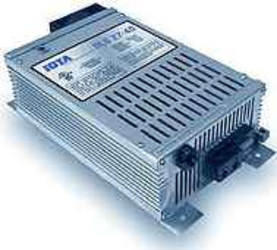
IOTA Engineering DLS-27-40 40A, 24V AC Converter/Charger
| Item code | Brand name | Model number | Amps |
| IOTDLS27-40 | IOTA Engineering | DLS-27-40 | 40A |
 |
 |
 |
IOTA DLS2740
Battery Charger / Power Converter
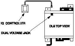
The DLS 27-40 features a Two-Step Voltage Jack which allows switching from a long-term float voltage to an increased rapid charge by simply inserting the dual voltage plug (included) into the jack.
The DLS 27-40 is also available with an IQ smart-controller already integrated into the unit which converts the charger into a 3-stage "smart" charger, increasing the performance of your DLS 27-40.
27V thru 48V DLS Power Converters/Battery Chargers provide quality service and protection for a wide range of voltage applications. Each features the Dual Voltage Jack for easy two-step charging, external and internal IQ controller option compatibility, and are backed by our standard Two-Year Warranty. Using state-of-the-art, switch-mode technology, the DLS Power Supply series is engineered with the user and variable environmental conditions in mind. Extra care has been given to insure many years of service-free operation, even when subjected to extremely harsh conditions. Batteries are charged quickly and efficiently without over charging and pumps, motors, and fans operate perfectly for prolonged life. IOTA Engineering uses advanced switch mode technology to bring to market highly sophisticated electronic converter/power supplies at appealing affordability. Exceptionally clean DC output insures pumps, motors, fans, and lights work perfectly. This means longer life for any connected load; virtually no AC ripple to cause static or premature failure of radio or television equipment. The DLS series converter/charger quickly and efficiently charges batteries from the full rated output of the DLS. The DLS then maintains the batteries, only putting into the battery what is required by load or self discharge, cutting back to milliamps as the battery requires. Low and transient AC line voltage is a major cause of converter/power supply failure. The DLS series converter/power supply is protected against low line voltage, as well as spikes coming from the AC power source or from improperly adjusted generators. The DLS series converter/power supply meets F.C.C. criteria, minimizing radio and television equipment interference, especially on the lower frequency bands. The DLS series converter/power supply can be used with or without a battery. When used as a converter/power supply, the DLS model will only supply what is required by the load. When not in use it is essentially off, reducing electricity usage. Even in its subcompact size, the DLS series converter/power supply, at full load, has an operating temperature half that of some switch mode electronic models. This means substantially longer life and safer operation. Tight line-load regulation ensures that the output voltage holds steady from no load to full load. This keeps pumps, motors, and lights working at the correct voltage even during brown out situations. Proportional Fan Circuitry provides an extra measure of protection. During times of heavy load demands, the automatic circuitry will activate the fan before thermal stress can occur on any internal components. Reliability and durability is built into all DLS models. In the event the batteries or the DLS unit is wired incorrectly, the DLS converter/power supply is protected from damage. External fuses can be quic
|
|||||||
The DLS series power converter/battery charger is designed with high quality components to help ensure years of continuous use. The DLS series is protected by multiple protection features for a long, trouble-free life. 1) Reverse Battery Polarity Protection. 2) Brown-Out Input Protection. 3) Over-Current Protection - cycle by cycle peak limiting as well as rated current limiting to maximize the life of the converter. 4) Over-Temperature Protection. In addition, it is designed with a unique “proportional” fan control circuit. Fan speed is directly proportional to the converter’s internal ambient temperature. This enables the fan to turn on and off very slowly, minimizing unwanted fan-starting noise. WARRANTY The DLS series power converter/battery charger is warranted from defects in materials or workmanship for two years from date of retail purchase, and limits the remedies to repair or replacement. This warranty is valid only in the continental United States and Canada. INSTALLATION GUIDELINES There are no components within the DLS unit that, in their normal operation, produce arcs or sparks. However, all electronic devices have some potential for generating sparks in the event of failure. Therefore, never install this device in the same compartment with flammable items such as gasoline or batteries.
MOUNTING LOCATION
DLS INSTALLATION
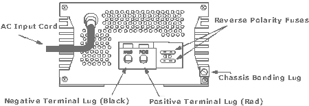
120 VOLT A.C. INPUT REVERSE POLARITY FUSES CHARGE CONTROLLER OPTIONS Charge Controller Options are designed for DLS units that DO NOT have the IQ SMART CONTROL FEATURE internally integrated. It is not necessary to utilize the Dual Voltage Jack or External IQ Controller for IQ-integrated DLS units.
|
|||||||
PDF Documentation
DLS Manual
DLS 55 Mounting Diagram
DLS Specifications
Warranty


 TWO-STEP VOLTAGE JACK
 IQ SMART CHARGER

