Hot breakers

3 Posts
Mar 6, 2009 05:07 am
Hot breakers

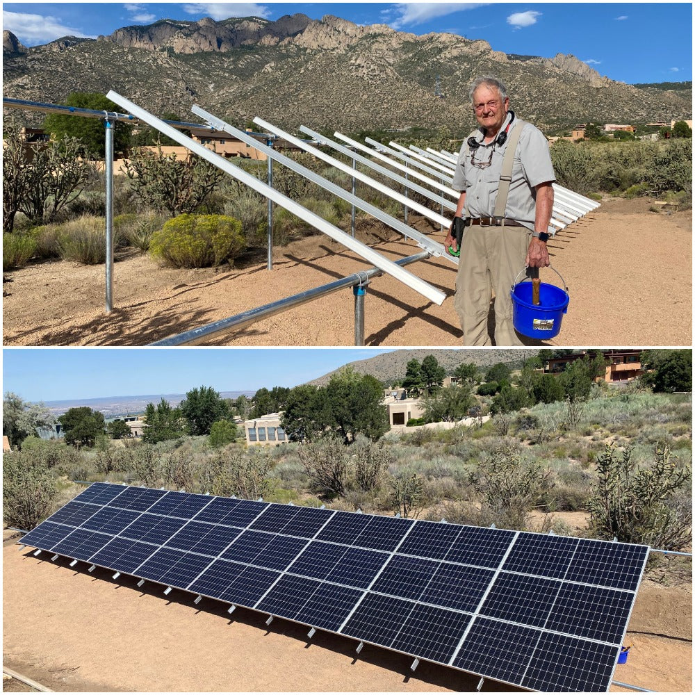
I’ve just put in a 14-solar panel system with a DR1524 inverter.  Everything went very well except that we had a bit of a problem with wiring getting warm

We are running two sets of 7 pcs 170W, 24V panels through two parallel sets of breakers (1 breaker for each panel) and controllers, into the battery system.  Inverter comes of course from there.

The controllers are Morningstar Tristar charge controllers - TS-60 - 020-01108-NL.   Each panel comes down to its own 15A cartridge fuse and the outputs are bussed to the controller via a 63A breaker (the solar breaker, I have called it).   From the controller, power goes through another 63A breaker (the battery breaker) to the battery bank via the battery +ve bus in the E-panel. 

The 63A breakers are Midnite 63A 125VDC din rail mnt breaker. 

The system was checked in bright sunlight to give total 84 amps of charge, and we read in fact 43 amps on each side at one point.  The left hand box and controller I have called “A”. and the right hand “B”.

I did the sums on the wire sizes and have used 10mm (8AWG) for all these 63A wiring runs. The longest one is no more than 18 inches (battery breaker to E-panel).  All the other runs are much shorter.  The panel wires are max 20 feet which my wire size calculatoir says is fine with 2.5mm cable.  In fact I could go up to 28 feet, it says, using a 3% wire loss.  So wire size should be OK.

When we checked the wiring heat, the wires from the panels were cold.  But we found that the wires carrying current to and from both the solar and battery breakers on both A & B were at the top end of warm.  Not hot, but definitely warm.  The wires carrying current from the battery breakers to the E-panel were not very warm, but still a bit over temperature.  When we felt the 63A breakers these were definitely hot to the touch, though not unbearably so. They were running at only 66% capacity (max 43 amps).

It therefore seems that the source of the heat was the breakers.   The A side was a bit cooler than the B side, but still hotter than we would have expected.  After some discussion, we decided to bridge the solar breaker on the hottest side, B.  When we did this, the other, battery, breaker cooled down and so did the wiring.  Now it was the A side which was hottest.

This was with the breaker box open.  I was concerned that when we put the covers on, the problem would get worse.  This is tropics, with air temperature in the upper 80’s day-time, when the current is flowing.  As a result we permanently wired both sides to bridge the solar breaker and take it out of the system.

The system was watched and we found both sides battery breakers to be much cooler and no warm wires.

That’s the history.  The breakers seemed to be the heat source.  Why?

Because each Flexware box would only hold 6 panel cartridges, and we have 14 panels, we modified the boxes to take 7 cartridge fuses and fitted the two 63A breakers beside them on the same DIN rail.  Are they too close together?  I don’t think so – these things get stacked in much higher numbers than 2. 

Is there a possibility that we have the feeds the wrong way round?  Is there an input and output in these breakers, or doesn’t it matter?  Before installation I researched this point but could nowhere find any advice specifically stating that the input should be at the top, for instance.  At the end of the day, a breaker trips when it’s overloaded.  Whichever side the overload is coming from, it will trigger the breaker?  Or am I incorrect here – does the load have to come through the trigger before entering the breaker points?  And if wired the other way, could this make a breaker overheat?  We are coming from the solar bus into the top of the solar breaker, out to the controller, but from the controller into the bottom of the battery breaker and out through the top to the batteries.

Anyone got any ideas?  The system is working fine now but I want to know for next time.

Guyanapete
 
163 Posts
Mar 7, 2009 09:44 pm
Re: Hot breakers

I believe your problem is running 43+ amps through a #8 awg wire. Even at only 18" in length I think the wire is too small. The overheated wire would then dissipate heat through the breaker making it hot. I would use #4 awg for the battery run or try four #8 awg wire wrapped together.
 
33 Posts
Mar 7, 2009 11:34 pm
Re: Hot breakers

Agree with John. You are going to get a good temperature rise on 8 guage at anything over 24 amps. You will get slight warming on 6 guage and if you go 4 guage it will stay close to room temperature.

If your going to use too small of wire you need to become a power company and get other people to pay for it. Smiley
 
3 Posts
Mar 8, 2009 07:29 am
Re: Hot breakers

Many thanks guys!  Back to the drawing board.

There is clearly something I’m missing here since if I use the AltE wiring sizing calculator, it gives me only a 1.32mm2 cable, for which the next size up is a 14 gauge which 2.08mm2.  Way too small.

Using the calculator formula, a 2 ft cable, running 44A at 24V, with a 3% voltage drop equates to (2 * 44)/(3 * 24) which is for sure a VDI of 1.22.  From the table, or using VDI * 1.1, that is a 1.34mm2 cable.

Looking at the Outback controller manual wire run tables, a #8 gives me 6 feet of run at 50 amps.  This table gives much larger sizes than the AltE calculator.

What I’m trying to get at here is just what is the calculation for wire sizing then, since you guys are going much bigger than the Outback tables or the AltE calculator.

Let me know your thoughts,

Cheers


Guyanapete
 
Mar 8, 2009 02:07 pm
Re: Hot breakers

A simple formula that I use for sizing PV source circuits is as follows.
Take the sum of the PV modules rated short circuit amperages and multiply by 156%.
In your case I believe that would be somewhere in the vicinity of, 5.47 Isc.
7 X 5.47 x 156% = 59.73
This would be the number I use for any other calculations concerning the sizing of wire. In addition to line loss, other considerations are; type if insulation, temperature deratings, number of conductors in a conduit, etc., etc.
But thats just my way.
Here is a link with a lot of useful information concern PV practices and the NEC.
http://photovoltaics.sandia.gov/docs/John_Wiles_Code_Corner.htm

Um, is the 63 amp breaker 1 - two pole or 2 - single pole breakers? If it is 1 - two pole breaker there might be some eddying of currents going on internally causing the heat. Heat in any conductors (not just the wires) of electricity is typically a sign that there is resistance due to poor conductivity. Check the temperature ratings of the breakers. It might pay to purchase or barrow a temperature probe. Such as, but not limited to, this one.
http://www.calex.co.uk/index.php?option=com_content&task=view&id=49&Itemid=63
 
578 Posts
Mar 9, 2009 11:04 am
Re: Hot breakers

hi everyone, please let us/me know when you suspect problems with any of the calculators.  I will be looking into the wire size one this week, as i did not know who wrote it or when.

the other note i should mention, is that the din rail circuit breakers from cbi (midnite and outback) are both rated to 150vdc now, but they can only take 6awg as far as i know.

cheers,

james
altE staff


AltE
"Making Renewable Do-able"
http://www.altEstore.com/

Tel: 877.878.4060 x107  or +1.978.562.5858 x107
Fax: 877.242.6718  or +1.978.562.5854
 
33 Posts
Mar 9, 2009 03:33 pm
Re: Hot breakers

Many thanks guys!  Back to the drawing board.

There is clearly something I’m missing here since if I use the AltE wiring sizing calculator, it gives me only a 1.32mm2 cable, for which the next size up is a 14 gauge which 2.08mm2.  Way too small.

Using the calculator formula, a 2 ft cable, running 44A at 24V, with a 3% voltage drop equates to (2 * 44)/(3 * 24) which is for sure a VDI of 1.22.  From the table, or using VDI * 1.1, that is a 1.34mm2 cable.

Looking at the Outback controller manual wire run tables, a #8 gives me 6 feet of run at 50 amps.  This table gives much larger sizes than the AltE calculator.

What I’m trying to get at here is just what is the calculation for wire sizing then, since you guys are going much bigger than the Outback tables or the AltE calculator.

Let me know your thoughts,

Cheers

Guyanapete

My thoughts are these. Solar panels use way to small of bus wires when the savings is so negligible considering all the other components in the system. Electrical engineers are are far to accustomed to using voltage dropped wire heating guage sizes which aren't really applicable in solar engineering.

Here's a good table.
http://www.powerstream.com/Wire_Size.htm

Doubling the thickness of all bus tabbings on your panels would increase throughput significantly only cost a few dollars and make no difference in thickness or ease of production or anything. Everyone needs to pressure solar panel makers to go thicker on cell tabbings.

As for interconnects. Try for .1 max volt drop for every run. If you can save money by not doing that make sure the savings are significant. Pure copper wire is a pain to work with so many manufactures alloy a bit because copper always work hardens IMMEDIATELY. If you take the precious metals you get this.
Copper- Work hardens completely. Hard to work with and you will almost never see it in it's pure state because of this.
Silver- Work hardens middle of the road. Have to work with it a bit to get it to work harden.
Gold- Will not work harden. You can pound it and pound it and pound it and work it into THREADS. It just won't work harden at triple 9 purity.

So good to know exactly what the wire is and make a few small adjustments and try to avoid using voltage drop formulas in solar applications, or understand that it will turn your wires into heating elements.
 
3 Posts
Mar 10, 2009 08:41 am
Re: Hot breakers

Hello guys,

First of all, many thanks for your patience and time in explaining all this to me.  I will certainly pass this information on to all concerned at my end. 

It’s very interesting that this “phenomena” occurs- almost as if we are dealing with another animal here, which does not obey normal rules.  But – as you say – the rules were not made for this application. 

The more I get into the detail and physics, the more interesting I find things.  I’m now considering using a #2 for all the bus interconnects, which should take care of the problem.  Cost is minimal as the runs are in some cases only inches.

Thanks very much again,


Guyanapete


Disclaimer and Disclosure

The Alternative Energy Store, Inc reserves the right, within its sole discretion, to refuse or delete any posting or portion thereof, or terminate or block the access to this forum.

The opinions and statements posted on this forum are the opinions and statements of the person posting same, and do not constitute the opinion or act of the Alternative Energy Store, Inc (AltE). The Alternative Energy Store, Inc does not endorse or subscribe to any particular posting. No posting shall be construed as the act or opinion of the Alternative Energy Store, Inc.

Click here for BBB Business Review

McAfee SECURE sites help keep you safe from identity theft, credit card fraud, spyware, spam, viruses and online scams
Desktop Website | Mobile Website

Share

Click on an icon to share! If you don't see the method you want, hover over the orange "+".

Feedback

What can we do to help you?

Please enter a summary
Sorry, the copyright must be in the template.
Please notify this forum's administrator that this site is using an ILLEGAL copy of SMF!
Copyright removed!!