#3 -
Renewable Energy > Technical Discussion: Other > Hot breakers
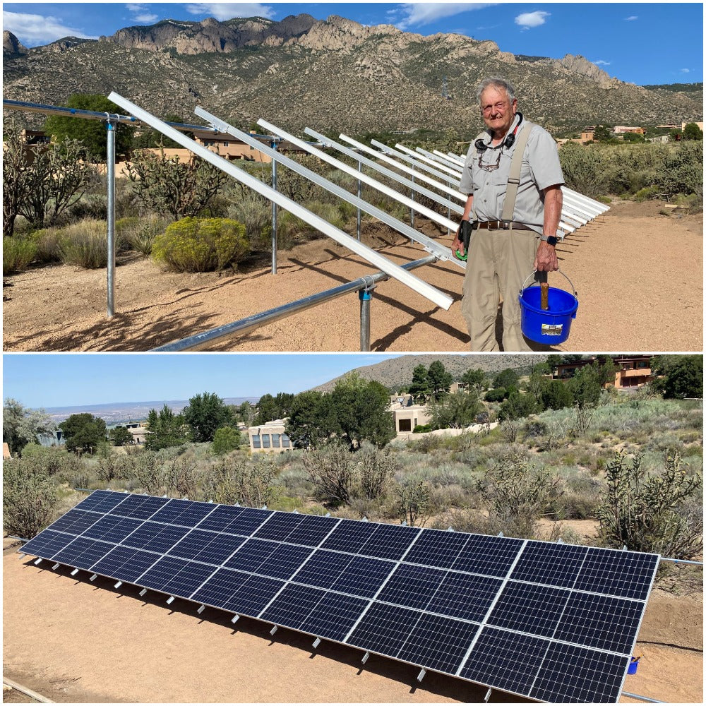
I’ve just put in a 14-solar panel system with a DR1524 inverter. Everything went very well except that we had a bit of a problem with wiring getting warm
We are running two sets of 7 pcs 170W, 24V panels through two parallel sets of breakers (1 breaker for each panel) and controllers, into the battery system. Inverter comes of course from there.
The controllers are Morningstar Tristar charge controllers - TS-60 - 020-01108-NL. Each panel comes down to its own 15A cartridge fuse and the outputs are bussed to the controller via a 63A breaker (the solar breaker, I have called it). From the controller, power goes through another 63A breaker (the battery breaker) to the battery bank via the battery +ve bus in the E-panel.
The 63A breakers are Midnite 63A 125VDC din rail mnt breaker.
The system was checked in bright sunlight to give total 84 amps of charge, and we read in fact 43 amps on each side at one point. The left hand box and controller I have called “A”. and the right hand “B”.
I did the sums on the wire sizes and have used 10mm (8AWG) for all these 63A wiring runs. The longest one is no more than 18 inches (battery breaker to E-panel). All the other runs are much shorter. The panel wires are max 20 feet which my wire size calculatoir says is fine with 2.5mm cable. In fact I could go up to 28 feet, it says, using a 3% wire loss. So wire size should be OK.
When we checked the wiring heat, the wires from the panels were cold. But we found that the wires carrying current to and from both the solar and battery breakers on both A & B were at the top end of warm. Not hot, but definitely warm. The wires carrying current from the battery breakers to the E-panel were not very warm, but still a bit over temperature. When we felt the 63A breakers these were definitely hot to the touch, though not unbearably so. They were running at only 66% capacity (max 43 amps).
It therefore seems that the source of the heat was the breakers. The A side was a bit cooler than the B side, but still hotter than we would have expected. After some discussion, we decided to bridge the solar breaker on the hottest side, B. When we did this, the other, battery, breaker cooled down and so did the wiring. Now it was the A side which was hottest.
This was with the breaker box open. I was concerned that when we put the covers on, the problem would get worse. This is tropics, with air temperature in the upper 80’s day-time, when the current is flowing. As a result we permanently wired both sides to bridge the solar breaker and take it out of the system.
The system was watched and we found both sides battery breakers to be much cooler and no warm wires.
That’s the history. The breakers seemed to be the heat source. Why?
Because each Flexware box would only hold 6 panel cartridges, and we have 14 panels, we modified the boxes to take 7 cartridge fuses and fitted the two 63A breakers beside them on the same DIN rail. Are they too close together? I don’t think so – these things get stacked in much higher numbers than 2.
Is there a possibility that we have the feeds the wrong way round? Is there an input and output in these breakers, or doesn’t it matter? Before installation I researched this point but could nowhere find any advice specifically stating that the input should be at the top, for instance. At the end of the day, a breaker trips when it’s overloaded. Whichever side the overload is coming from, it will trigger the breaker? Or am I incorrect here – does the load have to come through the trigger before entering the breaker points? And if wired the other way, could this make a breaker overheat? We are coming from the solar bus into the top of the solar breaker, out to the controller, but from the controller into the bottom of the battery breaker and out through the top to the batteries.
Anyone got any ideas? The system is working fine now but I want to know for next time.
Guyanapete