
So, you just got a solar panel that has no polarity labels. How can you figure out the proper polarity, which terminal or wire is plus and which is minus? Here’s a couple of easy tips than can even be done inside, away from the sun.
Look at the diode
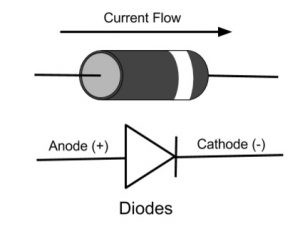
The negative of the bypass diode (i.e. the cathode) in a bypass diode is located with the positive of the solar panel.
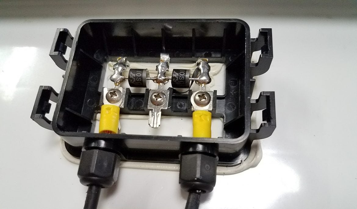
If you can open up the junction box, you will likely see at least one bypass diode inside. This is to help prevent power loss due to shading of a 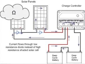 solar panel. It provides an alternative path for the current when the panel is shaded, and therefore at a higher resistance. There may only be one diode, which bypasses the whole panel in a solar array, as seen in the diagram, or multiple diodes, bypassing cells within the solar panel itself, as seen in the picture.
Diode stripe (cathode) pointing to positive
The striped cathode of the diode will be pointing towards the positive side of the solar panel. The other side is the negative.
For more information on diodes in a solar system, watch our video Blocking and Bypass Diodes in a Solar Panel Systems.
Measure with volt meter
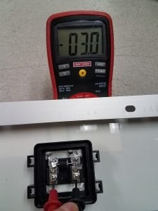
Reverse Polarity
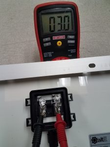
Correct Polarity
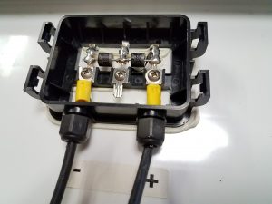
Another way to find the polarity of the solar panel is to check with a volt meter. A simple voltage reading will show you the polarity of a solar panel, even when inside.
To measure across the solar panel terminals or wires, put the red positive meter lead on one side, and the black negative on the other. Set the volt meter to read DC Volts. If the volt meter shows a negative number, indicated by a minus symbol, the leads are the wrong direction. Switching them over shows a positive number, with no negative symbol, so the red meter lead is on the positive, and the black meter lead is on the negative.
Note in the pictures you can also see the bypass diode in the junction box. You can see the stripe of the diode is on the side with the red positive lead, proving the previous method correct.
The solar panel is only putting out 3 volts, because it is upside down inside the building, and just getting a little light hitting it. But it is enough to get a correct polarity reading. If you were to try to measure current, there likely would be none with such little light, as voltage is less affected by the intensity of light than current is.
Check out our videos online for more tips and tricks for your solar system.
Can you let me know the calculation based on which sizing of an Off-Grid Solar System & battery backup is done.I have seen the Alt-E calculator but for a better understanding I wish to know the calculation (working).Would appreciate if you could show for my knowledge.
This is the calculation I use. It is slightly different from our calculator, but very close.
Daily watt hours / sun hours / .6 system losses = minimum solar watts
Daily watt hours / inverter efficiency x days without sun x temperature compensation / 50% depth of discharge (for lead acid) / battery bank voltage = battery bank amp hours.
Examples:
2000Wh / 3 sun hours /.6 = 1111W. Probably round up to 1200W of solar.
2000Wh / .9 x 3 days x 1.19 (50F) / 50% DoD / 24V = 661Ah 24V Battery bank
Nice information its little out of my knowledge but you explain its clear, thank you
“The striped cathode of the diode will be pointing towards the positive side of the solar panel. The other side is the negative.”
Are you sure about that?
Yes, quite sure. Take a look at the pictures. It is counter intuitive. But it is set up like that to allow the flow of electricity to bypass that section of the panel. So the negative of the diode is pointing to the positive of the panel.
can I charge a 200v lithium pack with 3 solar thin film panel 36v thanks john
Probably not. What is that 36V, is is Voc, Vmp, or nominal? With most charge controllers, you need to have a Vmp higher than the voltage of the battery bank. If that is 36Vmp x 3 in series, you are still only at 108Vmp.
Additionally, you need a charge controller designed for the voltage of the battery bank. I don’t know of any that does 200VDC. Not that there isn’t one, I just don’t know of any.
thanks for the info, I will keep looking john