

A photovoltaic (PV) module or solar electric panel is the smallest replaceable unit in a PV array. The module is an integral unit that provides support for a number of PV cells connected electrically and protected from the elements. The electrical output of the module depends on the size and number of cells, their electrical interconnection, and, of course, on the environmental conditions to which the module is exposed. Solar electric panels come in all shapes and sizes, and may be made from different materials. However, the most commonly used module is a “glass-plate-sandwich” that has 36 PV cells connected in series to produce enough voltage to charge a 12 volt battery. The purpose of the structure is to provide a rigid package and protect the inter-cell connections from the environment. Plus (+) and minus (-) connectors are located on the back of the module for interconnection. The modules may have an individual metal frame or be protected by a rubber gasket and intended for installation in a larger mounting system designed to hold several modules.
Did you know?
MPPT solar charge controllers are specially designed to ensure your solar panel operates at the maximum power point. Using this type of solar charge controller can increases charging efficiency by as much as 30%.
There are four factors that determine any solar electric panel’s output: efficiency of the photovoltaic cells, the load resistance, solar irradiance, and cell temperature. The solar cell efficiency is set by the manufacturing process; today’s commercially available modules reach efficiencies up to about 19%. The load resistance determines where the module will operate on the current and voltage (I-V) curve. The obvious preferred operating point is where maximum power (power is calculated by multiplying the current times the voltage) is generated, called the peak power point. Study the I-V curve shown below. This curve represents the output of any PV generator, from a cell to the largest array.
The I-V curve
For a given solar cell area, the current generated is directly proportional to solar irradiance (S) and is almost independent of temperature (T). Thus, as the sun’s brightness increases the output voltage and power decreases as temperature increases. The voltage of crystalline cells decreases about 0.5 percent per degree centigrade temperature increase. Therefore, arrays should be mounted in the sunniest place (no shading) and kept as cool as possible by ensuring air can move over and behind the array.
Shade and Solar PV Panels
PV modules are very sensitive to shading. Unlike a solar thermal panel which can tolerate some shading, many brands of PV modules cannot even be shaded by the branch of a leafless tree.
Shading obstructions can be defined as soft or hard sources. If a tree branch, roof vent, chimney or other item is shading from a distance, the shadow is diffuse or dispersed. These soft sources significantly reduce the amount of light reaching the cell(s) of a module. Hard sources are defined as those that stop light from reaching the cell(s), such as a blanket, tree branch, bird dropping, or the like, sitting directly on top of the glass. If even one full cell is hard shaded, the voltage of that module will drop to half of its unshaded value in order to protect itself. If enough cells are hard shaded, the module will not convert any energy and will, in fact, become a tiny drain of energy on the entire system.
Partial-shading even one cell of a 36-cell module will reduce its power output. Because all cells are connected in a series string, the weakest cell will bring the others down to its reduced power level. Therefore, whether ½ of one cell is shaded, or ½ a row of cells is shaded as shown above, the power decrease will be the same and proportional to the percentage of area shaded, in this case 50%.
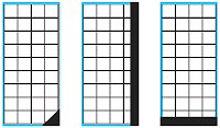
Examples of partial cell shading that will reduce a solar electric panel’s power by 50%.
When a full cell is shaded, it can act as a consumer of energy produced by the remainder of the cells, and trigger the module to protect itself. The module will route the power around that series string. If even one full cell in a series string is shaded, as seen on the right, it will likely cause the module to reduce its power level to ½ of its full available value. If a row of cells at the bottom of a module is fully shaded, as seen in the figure above, the power output may drop to zero. The best way to avoid a drop in output power is to avoid shading whenever possible.
However, since it is impossible to prevent occasional shading, the use of bypass diodes around series-connected modules is recommended. Almost all panels of the solar panels that are offered come with these diodes integrated right into the module itself. You do not need bypass diodes if all the modules are in parallel, i.e., a 12V array using 12V modules and many designers do not use them on 24V arrays. However for array voltages higher than 24V, bypass diodes should be used around each module to provide an alternative current path in case of shading. Many module manufacturers will provide modules with the bypass diodes integrated into the module junction box. If you need to connect modules in series, ask the supplier for this feature. Using bypass diodes may postpone failure, but it does not prevent the loss of energy production from the shading. It is important to check for potential shading before installing the PV array. Consider the seasonal changes in foliage and sun angle. After installation, the area must be maintained to prevent weeds or tree branches from shading the array.
Did you know?
Solar panels are increasingly being manufactured to minimize the performance reduction partial shading causes. Modules with “split” or “twin” design operate as two independent halves within a single module – so if one half is in partial shade, only that half’s performance will be reduced and the other half will be unaffected.
Solar PV Panel Safety
All solar electric panels should have durable connectors on the module. The connectors should be sturdy, and the method of attaching the wire should be simple, yet provide a secure connection. Most modules have sealed junction boxes to protect the connections. Field testing experience shows that PV cells and connections between cells within the module laminate rarely fail. Most problems occur in the module junction box where the interconnections between modules are made. These can often be repaired in the field without replacing the module. Before buying a solar electric panel, look at the junction box and see if it is easy to make the connections. Are the terminals rugged and is there a place to connect bypass diodes? Is the junction box of good quality?
A switch or circuit breaker as part of a combiner box should be installed to isolate the PV array during maintenance. This same recommendation applies to the battery circuit so another switch or circuit breaker is required. Also circuit breakers are normally installed to isolate each load. Fuses are used to protect any current carrying conductor. Fuses and cables in the array circuit should be sized to carry the maximum current that could be produced by short-term “cloud focusing” of the sunlight – up to 1.5 times the short circuit current at 1,000 W/m2 irradiance. Slow-blow fuses or PV breakers are recommended. Only fuses rated for dc current should be used. (Automotive fuses should not be used.) All metal in a solar panel array should be grounded to help protect the array against lightning surges, and as an added safety feature for personnel working on the system. The negative conductor on most solar electric systems is also grounded to the same grounding electrode used for the equipment ground. Other disconnect and grounding requirements are given in the National Electrical Code (NEC). This code is intended to ensure that safe, durable solar electric systems are installed.
Solar PV Panel Orientation
A solar electric panel array can be mounted at a fixed angle from the horizontal or on a sun-tracking mechanism. The preferred azimuth for arrays in the northern hemisphere is true south. The decrease in energy production for off-south arrays roughly follows a cosine function, so if the azimuth of the array is kept to ±20° of true south, annual energy production is not reduced significantly. Some arrays are sited west of south to skew the production toward an afternoon peak load demand. For most locations, a tilt angle near the latitude angle will provide the most energy over a full year. Tilt angles of latitude ±15° will skew energy production toward winter or summer, respectively.
This drawing illustrates the path of the sun over the seasons. Remember when selecting a site for your solar panels to a pick a spot that is clear of shade from a minimum of 10AM to 2PM from December 21st (for locations north of the equator). Even a limb from a deciduous tress will substantially reduce your array’s power output.