Hi Tom & David,
Thanks for the encouragement!
Yes, the reason for the relay is to protect my batteries from discharging too low and damaging them or reducing their lifespan. Yes, the idea is an automated system I can walk away from which will monitor itself to protect the batteries from over-discharge. The Sundanzer freezer's default (not customizable) low-voltage cutout is 10.8V or 11.8V or something, which may protect the compressor, but still toasts my batteries! So I want to keep my AGM batteries at or above the 12.2V range (~50% so I've been told), to maximize their lifespan. Similarly, my Prosine 1000i inverter has a default (not customizable) low-voltage cutout of 10V - big help that is! Xantrex tech support tells me if I'd sprung for the expensive XW system inverter of course I could customize its low-voltage cutout, but for my small system that extra $3600+ isn't worth it (and they agreed).
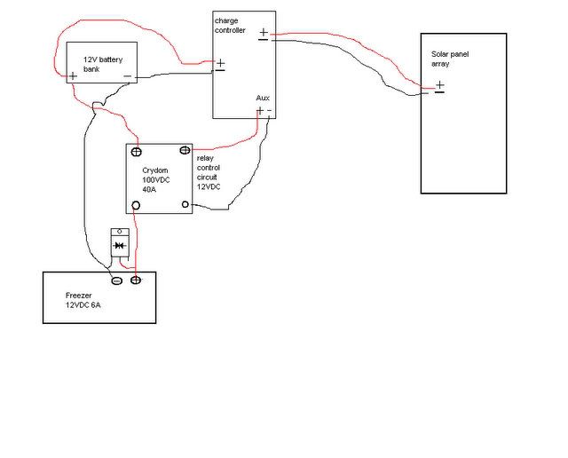
So my plan was to use a DC relay to run all of my loads, powered by the charge controller's Aux output. Unfortunately, finding a DC relay large enough to run my inverter through was not realistic (Amperage too high), so I opted for using 2 relays: one SSR is 12VDC up to 40A for my DC loads (some 12VDC emergency lighting, 12V freezer, 12V satellite internet system, totaling <=20A altogether); and a second SSR is 220VAC, wired between my inverter 220VAC output and my house 220VAC circuit breaker panel. I haven't tried the AC relay yet (does it need diodes too?), but first trying to work out the kinks with the DC relay.
Tom, there is nothing switching the Aux-to-relay power. The charge controller itself switches the Aux power on or off based on battery voltage levels. I'm currently set to "Active Lo", meaning the Aux port is normally powered (sending power to the control circuit of the DC relay, causing it to close). The charge controller cuts Aux port power (thereby opening the DC relay) when battery bank voltage falls to 12.2V or lower for 5mins or more. I've tested this scenario, letting my batt bank voltage drop to 12.2, and it operates correctly, cutting power to the relay control circuit until batt voltage returns to 12.4V for 5mins or more. According to the XW charge controller's instructions, the Aux port can be used to power a relay for this very purpose. But Xantrex tech support tells me "I've never heard of anyone using a setup like this, but it should work." Well, the XW's instructions (p. 1-8 "Auxiliary Output Functions") indicate this as a primary use of the Aux port!
Xantrex tech support suggested trying a C35 as a load controller if we can't get the DC relay setup to work, but then I still need to figure out how to manage my AC loads. Who knows, maybe the AC relay won't have these issues! Not going there yet though!
Grounding: sorry, my simple diagram doesn't show that I have a ground running from my charge controller to a ground bus bar, then to ground. (but not connected to the battery negative, in keeping with the XW instructions)
Relay: Is there a problem with the relay being continuously powered?
Running directly off battery: guys, we're thinking alike here! I will try running the freezer and satellite system straight from the batteries when I'm next in the village. It's not a good long-term solution, but it will help me isolate the problem (which seems to be some kind of interference caused by the relay, but we'll see).
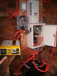
View from my power shed:

Regarding aux port output voltage: again, we're thinking alike! I just made a note to myself to try the aux port output voltage at 5VDC. The relay instructions indicate its control circuit can be powered by 3.5VDC up to 32VDC, so I'm going to try 5V and maybe 13V (Aux port can deliver 5-13VDC) and see if there are any differences. Hopefully something crazy like that will solve the interference issues!
Relay input Amperage: Here's an interesting note: Crydom's instructions state that the max input current is 1.6mA @5VDC or 28mA @32VDC (I'm not sure why the current is higher for higher voltage--I would expect higher voltage to require less current...anyway...). The XW's Aux port specifications say that it can deliver 5-13VDC and up to 200 mA! But the amperage output is not customizable on the XW. Could it be that the Aux port is sending way too much power (amperage) to the SSR? Or is the current (amperage) level going to be determined by whatever the SSR "needs" or "pulls", and no more? Next time I'm in the village I can put my Amp meter on that control circuit wire and see how much current is going through it to be sure...
Ferrite beads: could you explain? Never heard of 'em.
Charge controller status: I need to go through the display readings in the mornings of my subsequent tests and see what the XW's says its charge state is: does it say it's in float stage when I'm getting these low readings, or does it say its in bulk, but just delivering less-than-bulk output? I forgot to check this before. It should only be in bulk, because my batteries have always been in the 12.2-12.4 range in the mornings after having load(s) on the night before.
That's all for now. In the mean time, trying to get back to the village soon to run more tests and finish house-building!...

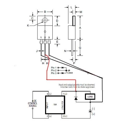
 If I can figure out how to post a .bmp I'll send a diagram of how I have these diodes wired now.
 Thanks!


 Especially if not properly grounded. You don't show any grounds in your diagram. This could also be the reason why you thought you needed to install some diodes. You have continuous power being supplied and it needs to go somewhere, so you may think that it needed to be stopped or redirected. Remember, Keep it Simple....


 ..there are some notes there about them being current limited (only draw what they need to operate) and being powered up continuously is one of the normal modes of operation.


 ) Well, here's the latest: Xantrex tech support is saying they're going to send me a new unit! (Of course, send to my U.S. address, then I'll have to get a hand-carry over here who-knows-when!) But in the mean time, I'm recording comparable output when set on "Manual" (MPPT off) and the reference voltage set to 60.0V (which I might have mentioned was the average reference voltage when the unit was on "Automatic", MPPT on). So I'm very happy to have a work-around for now, without having to try 2-stage charging. Of course with my family in the village I never get to "Float" anyway! ;o) But in 2 days they're back to town and I'll let 'er top off for a good while... Oh, and about the float timer issue you mentioned, I might mention that in my case, in the mornings when the unit was malfunctioning, the unit was still reading "Bulk", not "Float". Seems to be a different issue, eh?

 ) .
) .


